
Tuesday 11 June 2013
Wednesday 5 June 2013
Common TCP UDP Ports
| Application | Port | Protocol | Notes |
|---|---|---|---|
| HTTP | 80, 8080 | TCP | Hyptertext Transfer Protocol. Used by web browsers such as Internet Explorer, Firefox and Opera. |
| HTTPS | 443 | TCP, UDP | Used for secure web browsing. |
| IMAP | 143 | TCP | Email applications including Outlook, Outlook Express, Eudora and Thunderbird. |
| FTP | 20 to 21 | TCP | File Transfer Protocol. |
| SSH | 22 | TCP | Secure Shell protocol. Provides a secure session when logging into a remote machine. |
| Telnet | 23 | TCP | Used for remote server administration. |
| DNS | 53 | TCP, UDP | Domain Name System protocol for converting domain names to IP addresses. |
| NNTP | 119 | TCP | Network News Transfer Protocol, used for internet discussion groups. |
| NETBIOS | 137 to 139 | TCP, UDP | NETBIOS is used for file transfers between Windows machines. |
| SNMP | 161 to 162 | UDP | Simple Network Management Protocol. Used by network administrators for remote statistics and information gathering. |
| LDAP | 389 | TCP, UDP | Lightwight Directory Services Protocol, used for accessing centralized databases of users and computers. |
| Microsoft SQL Server | 1433 to 1434 | TCP, UDP | Database application. |
| MySQL | 3306 | TCP, UDP | Database application. |
| Oracle SQL | 1521, 1522, 1525, 1529 | TCP | Database application. |
| Microsoft Terminal Server / Citrix ICA | 1494, 1604 | UDP | Remote desktop application. |
| ICQ | 4000 | UDP | Instant messenger. |
| Yahoo Messenger | 5010 | TCP | Instant messenger. |
| AOL Instant Messenger | 5190 | TCP, UDP | Instant messenger. |
| PCAnywhere | 5632 | TCP, UDP | Remote desktop application. |
| VNC | 5800, 5900 | TCP | Virtual Network Computer, allows remote desktop functionality. |
| Kerberos | 88 | TCP, UDP | Used for user authentication, mainly on Windows systems. |
| POP3 | 110 | TCP | Post Office Protocool. For receiving email. |
| SMTP | 25 | TCP | Simple Mail Transfer Protocol, used for sending email. |
| RIP | 520 | UDP | Routing Information Protocol, part of the core internet infrastructure. |
| Microsoft PPTP | 1723 | TCP | Point-to-Point Tunneling Protocol, a VPN implementation. |
| Windows Media Streaming | 1755, 7007 | TCP, UDP | |
| Age of Empires | 2300 to 2400, 6073, 47624 | TCP, UDP | Multiplayer game. |
| Call of Duty | 20500, 20510, 28960 | TCP, UDP | Multiplayer game. |
| Counter-Strike | 1200, 27000 to 27015, 27020 to 27039 | TCP, UDP | Multiplayer game. |
| Doom 3 | 27650, 27666 | TCP, UDP | Multiplayer game. |
| Everquest | 1024, 6000, 7000 | TCP, UDP | Multiplayer game. |
| Far Cry | 49001 to 49002, 49124 | TCP, UDP | Multiplayer game. |
| FIFA | 3658, 10400 to 10499 | TCP, UDP | Multiplayer game. |
| Microsoft Flight Simulator | 2300 to 2400, 6073, 23456, 47624 | TCP, UDP | Multiplayer game. |
| Gamespy Arcade | 3783, 6515, 6500, 6667, 13139, 27900, 28900, 29900, 29901 | TCP, UDP | Game browser. |
| Gnutella | 6346 | TCP, UDP | P2P file sharing application. |
| GTA2 | 2300 to 2400, 47624 | TCP, UDP | Multiplayer game. |
| Half Life 2 | 1200, 27000 to 27015, 27020 to 27039 | TCP, UDP | Multiplayer game. |
| iTunes | 3689 | TCP, UDP | Music sharing application. |
| MSN Messenger | 1863, 5190, 6891 to 6901 | TCP, UDP | Instant messenger. |
| NBA Live | 3658, 9570, 18699 to 28600 | UDP | Multiplayer game. |
| Need For Speed | 80, 1030, 3658, 3659, 9442, 13505, 18210, 18215, 30900 to 30999 | TCP, UDP | Multiplayer game. |
| Net2Phone | 6801 | UDP | VoIP application. |
| NetFone | 10200 | TCP | VoIP application. |
| Neverwinter Nights | 5120 to 5300, 6500, 6667, 27900, 28900 | UDP | Multiplayer game. |
| NHL | 3658, 10300, 13505 | TCP, UDP | Multiplayer game. |
| No One Lives Forever | 2300 to 2400, 7000 to 10000, 27888 | TCP, UDP | Multiplayer game. |
| PhoneFree | 1034 to 1035, 2644, 8000, 9900 to 9901 | TCP, UDP | VoIP application. |
| Quake | 27650, 27910, 27950, 27952, 27960, 27965 | TCP, UDP | Multiplayer game. |
| Quicktime | 6970 to 7000 | TCP, UDP | Video streaming application. |
| Rainbow Six | 80, 2346 to 2348, 6667, 7777 to 7787, 8777 to 8787, 40000 to 42999, 44000, 45000 | TCP, UDP | Multiplayer game. |
| RealVNC | 5900 | TCP, UDP | Remote desktop application. |
| Remote Desktop | 3389 | TCP, UDP | Generic remote desktop protocol. |
| Shiva VPN | 2233 | TCP, UDP | Tunneling application. |
| Soldier of Fortune | 28910 to 28915, 20100 to 20112 | TCP, UDP | Multiplayer game. |
| Speak Freely | 2074 to 2076 | UDP | VoIP application. |
| Starcraft | 6112 | TCP, UDP | Multiplayer game. |
| TeamSpeak | 8767, 14534, 51234 | TCP, UDP | Online voice chat. |
| Tiger Woods PGA Tour | 80, 443, 9570, 13505, 20803, 20809, 32768 to 65535 | TCP, UDP | Multiplayer game. |
| Tight VNC | 5800, 5500, 5900 | TCP | Remote desktop application. |
| Tribes | 28000, 28001 | TCP, UDP | Multiplayer game. |
| Ultima Online | 5001 to 5010, 7775 to 7777, 7875, 8800 to 8900, 9999 | TCP | Multiplayer game. |
| Unreal Tournament | 7777 to 7788, 8080, 8777, 9777, 27900, 42292 | TCP, UDP | Multiplayer game. |
| Vonage | 5061, 10000 to 20000 | UDP | VoIP application. |
| VPhone | 11675 | TCP, UDP | VoIP application. |
| Warcraft | 6112 to 6119 | TCP, UDP | Multiplayer game. |
| WebcamXP | 8080, 8090 | TCP | Video sharing application. |
| Winamp Streaming | 8000 to 8001 | TCP | Audio streaming application. |
| Wingate VPN | 809 | TCP, UDP | Tunneling application. |
| World of Warcraft | 3724, 6112, 6881 to 6999 | TCP | Multiplayer game. |
| Worms Armageddon | 80, 6667, 17010 to 17012 | TCP | Multiplayer game. |
| XBox | 80, 1900, 3390, 3074, 3776, 3932, 5555, 7777 | TCP, UDP | Game appliance. |
| Azureus | 6881 to 6889 | TCP, UDP | P2P file sharing application. |
| DC++ | 411, 1025 to 32000 | TCP, UDP | P2P file sharing application. |
| Limewire | 6346 to 6347 | TCP, UDP | P2P file sharing application. |
Monday 3 June 2013
Understanding IPSec VPN
SA and Key Management with the IKE Protocol
The IKE protocol version 1, defined in RFC 2409, provides an automated mechanism for the exchange of keying material and secure negotiation of IPSec SAs. It is also possible to manually configure keying material and SAs on IPSec peers. Manual configuration of keying material and SAs is practical only in very small-scale environments, however, so it is not discussed further in this section.IKE is a hybrid protocol made up of elements of the following protocols:
- Internet Security Association and Key Management Protocol (ISAKMP, RFC 2408)
- Oakley Key Determination Protocol (RFC 2412)
- Secure Key Exchange Mechanism for the Internet (SKEME)
- Phase 1— Main or aggressive mode negotiation is used in this phase to establish a single bidirectional IKE SA between IPSec peers. This IKE SA, in turn, provides a secure means by which IPSec SAs can be established via quick mode negotiation.
- Phase 2— Quick mode negotiation occurs during this phase.
Overall ISAKMP Message Format
As previously mentioned, one element of IKE is ISAKMP, which provides (among other things) a message format for IKE negotiation.To understand IKE negotiation, it is important to have a basic understanding of the overall structure of the ISAKMP message, which is made up of a fixed header and a number of payloads. Figure 8-7 illustrates the relationship of the header to the payloads.
In Figure 1, the sample message consists of a header and four payloads. Each payload is indicated in the previous payload. For example, in the header, the Next Payload field indicates that the first payload in the chain is type X1. The Next Payload field in the X1 payload indicates that the second payload is of type X2, and so on. The final payload is indicated by the fact that the Next Payload field contains a value of 0.

Table 8-1 lists the payload types, together with their associated functions.
Table 8-1. Payload Types, Values, and Functions
|
Value
|
Payload Type
|
Description
|
|
0 |
NONE |
This is the final payload |
|
1 |
Security Association (SA) |
Contains security attributes ([sub] payload types 2 and 3) |
|
2 |
Proposal (P) |
Contains information used during SA negotiation |
|
3 |
Transform (T) |
Contains information used for SA negotiation (for example, IKE policy information) |
|
4 |
Key Exchange (KE) |
Used for key exchange between peers |
|
5 |
Identification (ID) |
Used to exchange identification information between peers |
|
6 |
Certificate (CERT) |
Used to send certificates or certificate-related information |
|
7 |
Certificate Request (CR) |
Used to request certificates |
|
8 |
Hash (HASH) |
Used to exchange data generated by hash function |
|
9 |
Signature (SIG) |
Used to exchange data generated by digital signature function (for nonrepudiation) |
|
10 |
Nonce (NONCE) |
Contains random data used to indicate liveliness and to protect against replay attacks |
|
11 |
Notification/Notify (N) |
Used to send informational data such as error conditions |
|
12 |
Delete |
Used to communicate SPIs of deleted SAs to peer |
|
13 |
Vendor ID (VID) |
Constant value to identify a vendor; can be used to implement vendor-specific features |
|
14–127 |
RESERVED |
Must be set to 0 |
|
128–255 |
Private Use |
Private use |
|
For more information on ISAKMP message structures, see RFC 2408. |
||
IKE Phase 1
As previously mentioned, the objective of IKE phase 1 is to establish a secure IKE SA and generate keys for IPSec. To this end, IPSec peers must agree on IKE parameters, exchange keying material, and authenticate each other.These objectives are achieved using one of the following negotiation modes:
- Main mode negotiation
- Aggressive mode negotiation
Main Mode Negotiation
Main mode negotiation involves the exchange of six messages between IPSec peers. The precise form of these messages is dictated by the method of peer authentication used.The three methods of authentication that can be used with IKE (in both main and aggressive modes) are:
- Preshared keys
- Rivest, Shamir, Adleman (RSA) signatures
- RSA encrypted nonces
Main Mode with Preshared Key Authentication
As mentioned, main mode consists of the exchange of three pairs or six messages between IPSec peers. Each of these pairs of messages serves a particular purpose.When a router or other system (called the initiator) wants to begin IKE negotiation, it sends a message to its peer. This message contains one or more IKE policy proposals (protection suites) containing parameters such as encryption algorithm, hash algorithm, authentication method, Diffie-Hellman group, and SA lifetime. These policy proposals are contained within an SA payload and its associated Proposal and Transform payloads. IKE policy is configured on Cisco routers using the crypto isakmp policy command.
The peer router (called the responder) examines the IKE policy information and attempts to find a match with its own locally configured IKE policies. Assuming the responder finds a matching IKE policy, it responds with a message indicating acceptance of one of the initiator's policies. Again, this proposal is contained with an SA payload. The peers have now negotiated an IKE policy.
The next two messages sent between the initiator and responder serve to exchange Diffie-Hellman public values, as well as nonces (random numbers). These values are exchanged in KE and NONCE payloads, respectively (see Table 8-1).
Diffie-Hellman is a public key algorithm that allows peers to exchange public key values over an insecure network, to combine the value received with their own private value, and through the wonders of modular exponentiation, to arrive independently at the same shared secret key.
The two nonce values (initiator's and responder's), together with the preshared key, are then used to generate the first of four session key values (SKEYID).
SKEYID is used, together with the shared secret key (from the Diffie-Hellman exchange) and other keying material, to derive three other session key values called SKEYID_d, SKEYID_a, and SKEYID_e. These session key values are used to derive keys for IPSec, authenticate further ISAKMP messages, and encrypt ISAKMP messages respectively.
At this stage, an IKE policy has been agreed upon (first two messages), keying material has been exchanged (second two messages), and session key values have been calculated.
All that now remains in phase 1 is for the two peers to exchange hash and identification values, contained in HASH and ID payloads. This is done during a third exchange of messages.
The peers then authenticate each other based on the hash values received. If the received hash value is the same as a hash value calculated locally, authentication succeeds. Note that the function of the ID payload is to identify the sender using, in this case, an IP address. The third exchange in phase 1 is encrypted (using SKEYID_e).
Figure 2 illustrates IKE phase 1 using preshared keys.

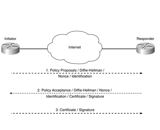
Main Mode with RSA Signature Authentication Using Digital Certificates
Main mode negotiation with RSA signature (digital certificate) authentication is very similar to main mode with preshared key authentication. The first two messages are again used to negotiate an IKE policy. The second two messages are again used to exchange keying material (Diffie-Hellman public values and nonces).The difference is the third exchange of messages. IKE peers using RSA signature authentication exchange identification, certificates, and signature. These elements are carried in the ID, CERT, and SIG payloads respectively.
Note that the SIG (signature) payload contains a digital signature. This provides nonrepudiation, which means that the system that sent the message cannot deny that it sent the message. The ID payload can contain the system's IP address, a fully qualified domain name (FQDN), or an X.500 distinguished name, for example.
Figure 3 illustrates main mode with RSA signature authentication using digital certificates.

Aggressive Mode Negotiation
Aggressive mode is faster but slightly less secure than main mode negotiation. It is faster because negotiation consists of only three messages, and it is slightly less secure because the ID payload is exchanged unencrypted.Aggressive Mode with Preshared Key Authentication
The first message sent by the initiator in aggressive mode consists of proposed IKE policies, its Diffie-Hellman public value, a nonce value, and identification. These are contained in the SA, KE, NONCE, and ID payloads, respectively. Note that all payloads exchanged during aggressive mode perform the same function as in main mode.The responder now replies with a message containing the accepted IKE policy, its Diffie-Hellman public value, a nonce, a hash used by the initiator to authenticate the responder, and identification. These are contained in SA, KE, HASH, and ID payloads.
Finally, the initiator sends the third and final message in the exchange. This consists simply of a hash (used by the responder to authenticate the initiator). The hash is contained in a HASH payload.
Figure 4 illustrates aggressive mode using preshared key authentication.

Aggressive Mode with RSA Signature Authentication Using Digital Certificates
Aggressive mode with RSA signature (digital certificate) authentication follows a similar pattern to that for preshared keys, with three messages being exchanged.The first message sent by the initiator contains policy proposals, its Diffie-Hellman public value, a nonce value, and identification. These are contained in SA, KE, NONCE, and ID payloads, respectively.
The responder replies with a message containing the accepted policy, its Diffie-Hellman public value, a nonce, identification, its certificate, and signature. These are contained in SA, KE, NONCE, ID, CERT, and SIG payloads.
Finally, the initiator sends a certificate and signature. These are contained in CERT and SIG payloads.
Figure 5 illustrates aggressive mode with RSA signature authentication using digital certificates.
IKE Phase 2
Once phase 1 is complete, and the IKE SA has been established, phase 2 can begin. The objective of phase 2 is to negotiate IPSec SAs.There is only one mode of negotiation within phase 2, called quick mode. Note that quick mode negotiation is protected by the IKE SA established in phase 1 (using SKEYID_a and SKEYID_e). Quick mode negotiation consists of the exchange of three messages between the initiator and the responder.
The first message in the exchange contains a hash, IPSec proposals, a nonce, and optionally, another Diffie-Hellman public value, and identities. These elements are contained in HASH, SA, NONCE, KE, and ID payloads, respectively.
The hash is used to authenticate the message to the responder. The IPSec proposals are used to specify security parameters, such as the security protocol (AH or ESP), encryption algorithm, hash algorithm, and IPSec tunnel mode (transport or tunnel) to be used for the IPSec SA. These parameters are configured on Cisco routers using the crypto ipsec transform-set command.
The nonce is used to protect against replay attacks. It is also used as additional keying material. The Diffie-Hellman public value is included in the message only if the initiator is configured for Perfect Forward Secrecy (PFS). Normally, keys used with IPSec SA are derived from keying material generated during IKE phase 1. This means that IPSec keys generated using PFS are more secure. PFS is configured using the set pfs {group 1 | group 2} command (within the crypto map).
Phase 2 identities are used to exchange selector information. These identities describe the addresses, protocols, and ports for which this IPSec SA is being established. On Cisco routers, phase 2 identities are configured using a crypto access list.
The responder then replies with a message containing a hash (used by the initiator to authenticate the responder), an IPSec proposal acceptance, a nonce value, and optionally, a Diffie-Hellman public value (if the responder supports PFS), and identities. These elements are again contained in HASH, SA, NONCE, KE, and ID payloads. The payloads in the message sent by the responder serve the same purpose as those sent by the initiator.
The initiator now sends a third and final message. This contains a hash (HASH payload), and it serves to acknowledge the responder's message and to prove that the initiator is alive (that is, that the first message sent by the initiator was not just a message replayed by another source).
Figure 6 illustrates quick mode negotiation.

Friday 31 May 2013

Wednesday 29 May 2013
Understanding "IP classless" command in Cisco Routers
IP Classless
Where the ip classless configuration command falls within the routing and forwarding processes is often confusing. In reality, IP classless only affects the operation of the forwarding processes in IOS; it doesn't affect the way the routing table is built. If IP classless isn't configured (using the no ip classless command), the router won't forward packets to supernets. As an example, let's again place three routes in the routing table and route packets through the router.Note: If the supernet or default route is learned via IS-IS or OSPF, the no ip classless configuration command is ignored. In this case, packet switching behavior works as though ip classless were configured.
router# show ip route
....
     172.30.0.0/16 is variably  subnetted, 2 subnets, 2 masks
D        172.30.32.0/20 [90/4879540] via  10.1.1.2
D       172.30.32.0/24  [90/25789217] via 10.1.1.1
S*   0.0.0.0/0 [1/0] via 10.1.1.3
Remembering that the 172.30.32.0/24 network includes the addresses
172.30.32.0 through 172.30.32.255, and the 172.30.32.0/20 network includes the
addresses 172.30.32.0 through 172.30.47.255, we can then try switching three
packets through this routing table and see what the results are. -
A packet destined to 172.30.32.1 is forwarded to 10.1.1.1, since this
is the longest prefix match.
-
A packet destined to 172.30.33.1 is forwarded to 10.1.1.2, since this
is the longest prefix match.
-
A packet destined to 192.168.10.1 is forwarded to 10.1.1.3; since
this network doesn't exist in the routing table, this packet is forwarded to
the default route.
-
A packet destined to 172.30.254.1 is
dropped.
This is the essence of classful routing: If one part of a major network is known, but the subnet toward which the packet is destined within that major network is unknown, the packet is dropped.
The most confusing aspect of this rule is that the router only uses the default route if the destination major network doesn't exist in the routing table at all.
This can cause problems in a network where a remote site, with one connection back to the rest of the network, is running no routing protocols, as illustrated.

The remote site router is configured like this:
interface Serial 0
     ip address 10.1.2.2 255.255.255.0
   !
   interface Ethernet 0
     ip address 10.1.1.1 255.255.255.0
   !
   ip route 0.0.0.0 0.0.0.0 10.1.2.1
   !
   no ip classless
With this configuration, the hosts at the remote site can reach
destinations on the Internet (through the 10.x.x.x cloud), but not destinations
within the 10.x.x.x cloud, which is the corporate network. Because the remote
router knows about some part of the 10.0.0.0/8 network, the two directly
connected subnets, and no other subnet of 10.x.x.x, it assumes these other
subnets don't exist and drops any packets destined for them. Traffic destined
to the Internet, however, doesn't ever have a destination in the 10.x.x.x range
of addresses, and is therefore correctly routed through the default route.
Configuring ip classless on the remote router resolves this problem by allowing the router to ignore the classful boundaries of the networks in its routing table and simply route to the longest prefix match it can find.
info source:
http://www.cisco.com/en/US/tech/tk365/technologies_tech_note09186a0080094823.shtml
Friday 17 May 2013
Understanding Bidirectional PIM
Understanding Bidirectional PIM
Bidirectional PIM (PIM-Bidir) is specified by the IETF in RFC
5015, Bidirectional Protocol Independent Multicast (BIDIR-PIM). It provides an alternative to other PIM modes, such as PIM sparse
mode (PIM-SM), PIM dense mode (PIM-DM), and PIM source-specific multicast
(SSM). In bidirectional PIM, multicast groups are carried across the
network over bidirectional shared trees. This type of tree minimizes
the amount of PIM routing state information that must be maintained,
which is especially important in networks with numerous and dispersed
senders and receivers. For example, one important application for
bidirectional PIM is distributed inventory polling. In many-to-many
applications, a multicast query from one station generates multicast
responses from many stations. For each multicast group, such an application
generates a large number of (S,G) routes for each station in PIM-SM,
PIM-DM, or SSM. The problem is even worse in applications that use
bursty sources, resulting in frequently changing multicast tables
and, therefore, performance problems in routers.
Figure 1 shows the traffic
flows generated to deliver traffic for one group to and from three
stations in a PIM-SM network.
Figure 1: Example PIM Sparse-Mode Tree

Bidirectional PIM solves this problem by building only group-specific
(*,G) state. Thus, only a single (*,G) route is needed for each group
to deliver traffic to and from all the sources.
Figure 2 shows the traffic
flows generated to deliver traffic for one group to and from three
stations in a bidirectional PIM network.
Figure 2: Example Bidirectional PIM
Tree

Bidirectional PIM builds bidirectional shared trees that are
rooted at a rendezvous point (RP) address. Bidirectional traffic does
not switch to shortest path trees (SPTs) as in PIM-SM and is therefore
optimized for routing state size instead of path length. Bidirectional
PIM routes are always wildcard-source (*,G) routes. The protocol eliminates
the need for (S,G) routes and data-triggered events. The bidirectional
(*,G) group trees carry traffic both upstream from senders toward
the RP, and downstream from the RP to receivers. As a consequence,
the strict reverse path forwarding (RPF)-based rules found in other
PIM modes do not apply to bidirectional PIM. Instead, bidirectional
PIM routes forward traffic from all sources and the RP. Thus, bidirectional
PIM routers must have the ability to accept traffic on many potential
incoming interfaces.
Designated Forwarder Election
To prevent forwarding loops, only one router on each link or
subnet (including point-to-point links) is a designated forwarder
(DF). The responsibilities of the DF are to forward downstream traffic
onto the link toward the receivers and to forward upstream traffic
from the link toward the RP address. Bidirectional PIM relies on a
process called DF election to choose the DF router for each interface
and for each RP address. Each bidirectional PIM router in a subnet
advertises its interior gateway protocol (IGP) unicast route to the
RP address. The router with the best IGP unicast route to the RP address
wins the DF election. Each router advertises its IGP route metrics
in DF Offer, Winner, Backoff, and Pass messages.
Junos OS implements the DF election procedures as stated in
RFC 5015, except that Junos OS checks RP unicast reachability before
accepting incoming DF messages. DF messages for unreachable rendezvous
points are ignored.
Bidirectional PIM Modes
In the Junos OS implementation, there are two modes for bidirectional
PIM: bidirectional-sparse and bidirectional-sparse-dense. The differences
between bidirectional-sparse and bidirectional-sparse-dense modes
are the same as the differences between sparse mode and sparse-dense
mode. Sparse-dense mode allows the interface to operate on a per-group
basis in either sparse or dense mode. A group specified as “dense”
is not mapped to an RP. Use bidirectional-sparse-dense mode when you
have a mix of bidirectional groups, sparse groups, and dense groups
in your network. One typical scenario for this is the use of auto-RP,
which uses dense-mode flooding to bootstrap itself for sparse mode
or bidirectional mode. In general, the dense groups could be for any
flows that the network design requires to be flooded.
Each group-to-RP mapping is controlled by the RP group-ranges statement and the ssm-groups statement.
The choice of PIM mode is closely tied to controlling how groups
are mapped to PIM modes, as follows:
- bidirectional-sparse—Use if all multicast groups are operating in bidirectional, sparse, or SSM mode.
- bidirectional-sparse-dense—Use if multicast groups, except those that are specified in the dense-groups statement, are operating in bidirectional, sparse, or SSM mode.
Bidirectional Rendezvous Points
You can configure group-range-to-RP mappings network-wide statically,
or only on routers connected to the RP addresses and advertise them
dynamically. Unlike rendezvous points for PIM-SM, which must de-encapsulate
PIM Register messages and perform other specific protocol actions,
bidirectional PIM rendezvous points implement no specific functionality.
RP addresses are simply locations in the network to rendezvous toward.
In fact, RP addresses need not be loopback interface addresses or
even be addresses configured on any router, as long as they are covered
by a subnet that is connected to a bidirectional PIM-capable router
and advertised to the network.
Thus, for bidirectional PIM, there is no meaningful distinction
between static and local RP addresses. Therefore, bidirectional PIM
rendezvous points are configured at the [edit protocols pim rp
bidirectional] hierarchy level, not under static or local.
The settings at the [edit protocol pim rp bidirectional] hierarchy level function like the settings at the [edit protocols
pim rp local] hierarchy level, except that they create bidirectional
PIM RP state instead of PIM-SM RP state.
Where only a single local RP can be configured, multiple bidirectional
rendezvous points can be configured having group ranges that are the
same, different, or overlapping. It is also permissible for a group
range or RP address to be configured as bidirectional and either static
or local for sparse-mode.
If a bidirectional PIM RP is configured without a group range,
the default group range is 224/4 for IPv4. For IPv6, the default is
ff00::/8. You can configure a bidirectional PIM RP group range to
cover an SSM group range, but in that case the SSM or DM group range
takes precedence over the bidirectional PIM RP configuration for those
groups. In other words, because SSM always takes precedence, it is
not permitted to have a bidirectional group range equal to or more
specific than an SSM or DM group range.
PIM Bootstrap and Auto-RP Support
Group ranges for the specified RP address are flagged by PIM
as bidirectional PIM group-to-RP mappings and, if configured, are
advertised using PIM bootstrap or auto-RP. Dynamic advertisement of
bidirectional PIM-flagged group-to-RP mappings using PIM bootstrap,
and auto-RP is controlled as normal using the bootstrap and auto-rp statements.
Bidirectional PIM RP addresses configured at the [edit
protocols pim rp bidirectional address] hierarchy level are
advertised by auto-RP or PIM bootstrap if the following prerequisites
are met:
- The routing instance must be configured to advertise candidate rendezvous points by way of auto-RP or PIM bootstrap, and an auto-RP mapping agent or bootstrap router, respectively, must be elected.
- The RP address must either be configured locally on an interface in the routing instance, or the RP address must belong to a subnet connected to an interface in the routing instance.
IGMP and MLD Support
Internet Group Management Protocol (IGMP) version 1, version
2, and version 3 are supported with bidirectional PIM. Multicast Listener
Discovery (MLD) version 1 and version 2 are supported with bidirectional
PIM. However, in all cases, only anysource multicast (ASM) state is
supported for bidirectional PIM membership.
The following rules apply to bidirectional PIM:
- IGMP and MLD (*,G) membership reports trigger the PIM DF to originate bidirectional PIM (*,G) join messages.
- IGMP and MLD (S,G) membership reports do not trigger the PIM DF to originate bidirectional PIM (*,G) join messages.
Bidirectional PIM and Graceful Restart
Bidirectional PIM accepts packets for a bidirectional route
on multiple interfaces. This means that some topologies might develop
multicast routing loops if all PIM neighbors are not synchronized
with regard to the identity of the designated forwarder (DF) on each
link. If one router is forwarding without actively participating in
DF elections, particularly after unicast routing changes, multicast
routing loops might occur.
If graceful restart for PIM is enabled and bidirectional PIM
is enabled, the default graceful restart behavior is to continue forwarding
packets on bidirectional routes. If the gracefully restarting router
was serving as a DF for some interfaces to rendezvous points, the
restarting router sends a DF Winner message with a metric of 0 on
each of these RP interfaces. This ensures that a neighbor router does
not become the DF due to unicast topology changes that might occur
during the graceful restart period. Sending a DF Winner message with
a metric of 0 prevents another PIM neighbor from assuming the DF role
until after graceful restart completes. When graceful restart completes,
the gracefully restarted router sends another DF Winner message with
the actual converged unicast metric.
The no-bidirectional-mode statement at the [edit
protocols pim graceful-restart] hierarchy level overrides the
default behavior and disables forwarding for bidirectional PIM routes
during graceful restart recovery, both in cases of simple routing
protocol process (rpd) restart and graceful Routing Engine switchover.
This configuration statement provides a very conservative alternative
to the default graceful restart behavior for bidirectional PIM routes.
The reason to discontinue forwarding of packets on bidirectional routes
is that the continuation of forwarding might lead to short-duration
multicast loops in rare double-failure circumstances.
Junos OS Enhancements to Bidirectional PIM
In addition to the functionality specified in RFC 5015, the
following functions are included in the Junos OS implementation of
bidirectional PIM:
- Source-only branches without PIM join state
- Support for both IPv4 and IPv6 domain and multicast addresses
- Nonstop routing (NSR) for bidirectional PIM routes
- Support for bidirectional PIM in logical systems
- Support for non-forwarding and virtual router instances
http://www.juniper.net/techpubs/en_US/junos/topics/concept/pim-bidir-overview.html
Wednesday 15 May 2013
Understanding Unicast Reverse Path Forwarding (uRPF)
Introduction
Network administrators can use Unicast Reverse Path Forwarding (Unicast RPF) to help limit the malicious traffic on an enterprise network. This security feature works by enabling a router to verify the reachability of the source address in packets being forwarded. This capability can limit the appearance of spoofed addresses on a network. If the source IP address is not valid, the packet is discarded. Unicast RPF works in one of three different modes: strict mode, loose mode, or VRF mode. Note that not all network devices support all three modes of operation. Unicast RPF in VRF mode will not be covered in this document.When administrators use Unicast RPF in strict mode, the packet must be received on the interface that the router would use to forward the return packet. Unicast RPF configured in strict mode may drop legitimate traffic that is received on an interface that was not the router's choice for sending return traffic. Dropping this legitimate traffic could occur when asymmetric routing paths are present in the network.
When administrators use Unicast RPF in loose mode, the source address must appear in the routing table. Administrators can change this behavior using the allow-default option, which allows the use of the default route in the source verification process. Additionally, a packet that contains a source address for which the return route points to the Null 0 interface will be dropped. An access list may also be specified that permits or denies certain source addresses in Unicast RPF loose mode.
Care must be taken to ensure that the appropriate Unicast RPF mode (loose or strict) is configured during the deployment of this feature because it can drop legitimate traffic. Although asymmetric traffic flows may be of concern when deploying this feature, Unicast RPF loose mode is a scalable option for networks that contain asymmetric routing paths.
Unicast RPF in an Enterprise Network
In many enterprise environments, it is necessary to use a combination of strict mode and loose mode Unicast RPF. The choice of the Unicast RPF mode that will be used will depend on the design of the network segment connected to the interface on which Unicast RPF is deployed.Administrators should use Unicast RPF in strict mode on network interfaces for which all packets received on an interface are guaranteed to originate from the subnet assigned to the interface. A subnet composed of end stations or network resources fulfills this requirement. Such a design would be in place for an access layer network or a branch office where there is only one path into and out of the branch network. No other traffic originating from the subnet is allowed and no other routes are available past the subnet.
Unicast RPF loose mode can be used on an uplink network interface that has a default route associated with it.
Unicast RPF Examples
Cisco IOS Devices
An important consideration for deployment is that Cisco Express Forwarding switching must be enabled for Unicast RPF to function. This command has been enabled by default as of IOS version 12.2. If it is not enabled, administrators can enable it with the following global configuration command: ip cefUnicast RPF is enabled on a per-interface basis. The ip verify unicast source reachable-via rx command enables Unicast RPF in strict mode. To enable loose mode, administrators can use the any option to enforce the requirement that the source IP address for a packet must appear in the routing table. The allow-default option may be used with either the rx or any option to include IP addresses not specifically contained in the routing table. The allow-self-ping option should not be used because it could create a denial of service condition. An access list such as the one that follows may also be configured to specifically permit or deny a list of addresses through Unicast RPF:
interface FastEthernet 0/0
ip verify unicast source reachable-via {rx | any} [allow-default]
[allow-self-ping] [list]
Addresses that should never appear on a network can be dropped by entering
a route to a null interface. The following command will cause all traffic
received from the 10.0.0.0/8 network to be dropped even if Unicast RPF is
enabled in loose mode with the allow-default option: ip route 10.0.0.0 255.0.0.0 Null0PIX/ASA/FWSM
Unicast RPF can be configured on the PIX Security Appliance, the ASA Security Appliance, the Catalyst 6500 switch, or the Cisco 7600 router Firewall Services Module on a per-interface basis with the following global command: ip verify reverse-path interface interface_nameTroubleshooting Unicast RPF
Cisco IOS Devices
The show cef interface interface_name command can be used to show that Cisco Express Forwarding and Unicast RPF have been enabled on an interface. The following response is an example of output for this command.router#show cef interface FastEthernet 0/0 FastEthernet0/0 is up (if_number 3) Corresponding hwidb fast_if_number 3 Corresponding hwidb firstsw->if_number 3 Internet address is 10.81.7.118/28 ICMP redirects are always sent Per packet load-sharing is disabled IP unicast RPF check is enabled Inbound access list is not set Outbound access list is not set Hardware idb is FastEthernet0/0 Fast switching type 1, interface type 18 IP CEF switching enabled IP CEF Fast switching turbo vector Input fast flags 0x0, Input fast flags2 0x0, Output fast flags 0x0, Output fast flags2 0x0 ifindex 1(1) Slot 0 Slot unit 0 Unit 0 VC -1 Transmit limit accumulator 0x0 (0x0) IP MTU 1500 router#
PIX/ASA/FWSM
The show ip verify statistics command can provide information about Unicast RPF statistics on a PIX/ASA/FWSM firewall. The following example shows 21 drops by Unicast RPF on the outside interface and 2738 packets dropped by Unicast RPF on the inside interface. Dropped packets should be investigated to determine their source and administrators should consider whether the packets indicate attempts to circumvent network security.R4-ASA5520a# show ip verify statistics interface outside: 21 unicast rpf drops interface inside: 2738 unicast rpf drops interface vpn: 0 unicast rpf drops R4-ASA5520a#
Thursday 9 May 2013
Understanding TCP connection flags
Cisco ASA Firewall TCP Connection
Flags.


When troubleshooting TCP connections through the
ASA, the connection flags shown for each TCP
connection provide a wealth of information about the
state of TCP connections to the ASA. This information can be used to
troubleshoot problems with the ASA, as well as problems elsewhere in the
network.
Here is the output of the show conn protocol tcp command,
which shows the state of all TCP connections through the ASA. These connections
can also be seen with the show conn command.
ASA# show conn
protocol tcp
101 in use, 5589 most
used
TCP outside
10.23.232.59:5223 inside 192.168.1.3:52419, idle 0:00:11, bytes 0, flags saA
TCP outside
192.168.3.5:80 dmz 172.16.103.221:57646, idle 0:00:29, bytes 2176, flags UIO
TCP outside
10.23.232.217:5223 inside 192.168.1.3:52425, idle 0:00:10, bytes 0, flags saA
TCP outside
10.23.232.217:443 inside 192.168.1.3:52427, idle 0:01:02, bytes 4504, flags UIO
TCP outside
10.23.232.57:5223 inside 192.168.1.3:52412, idle 0:00:23, bytes 0, flags saA
TCP outside
10.23.232.116:5223 inside 192.168.1.3:52408, idle 0:00:23, bytes 0, flags saA
TCP outside
10.23.232.60:5223 inside 192.168.1.3:52413, idle 0:00:23, bytes 0, flags saA
TCP outside
10.23.232.96:5223 inside 192.168.1.3:52421, idle 0:00:11, bytes 0, flags saA
TCP outside
10.23.232.190:5223 inside 192.168.1.3:52424, idle 0:00:10, bytes 0, flags saA
The next
picture shows the ASA TCP Connection flags at different stages of the TCP state
machine. The
connection flags can be seen with the show conn command on the ASA.
connection flags can be seen with the show conn command on the ASA.
TCP Connection Flag Values
Additionally, in order to view all of the possible
connection flags issue the show connection detail command
on the command line:
ASA# show conn
detail
84 in use, 1537 most
used
Flags: A − awaiting
inside ACK to SYN, a − awaiting outside ACK to SYN,
B − initial SYN from
outside, b − TCP state−bypass or nailed, C − CTIQBE media,
D − DNS, d − dump, E −
outside back connection, F − outside FIN, f − inside FIN,
G − group, g − MGCP, H −
H.323, h − H.225.0, I − inbound data,
i − incomplete, J −
GTP, j − GTP data, K − GTP t3−response
k − Skinny media, M −
SMTP data, m − SIP media, n − GUP
O − outbound data, P −
inside back connection, p − Phone−proxy TFTP connection,
q − SQL*Net data, R −
outside acknowledged FIN,
R − UDP SUNRPC, r −
inside acknowledged FIN, S − awaiting inside SYN,
s − awaiting outside
SYN, T − SIP, t − SIP transient, U − up,
V − VPN orphan, W −
WAAS,
X − inspected by
service module
Subscribe to:
Posts (Atom)
Cisco SD-WAN: Onboarding Controllers step by step (on-prem)
This configuration example only covers the process of installing the SD-WAN controller software images on a VMWare ESXI instance, establish...

-
This configuration example only covers the process of installing the SD-WAN controller software images on a VMWare ESXI instance, establish...
-
SSH Configuration: RX1(config)#int f0/0 RX1(config-if)#ip address 10.1.1.1 255.0.0.0 RX1(config-if)#no shut RX1(config-if)#exit RX1(c...
-
IP Classless Where the ip classless configuration command falls within the routing and forwarding processes is often confusing. In ...
